Wind Gearbox : the definitive guide to Vibration vs particle counters
These two CMS technologies are widely accepted as the best two methodologies for providing lead time to gearbox failure. Particularly in wind turbines, gearbox failure can have large cost implications for your Operations and Maintenance (O&M) budget. This guide covers the advantages and disadvantages of both systems, and how to build a business case for retrofit or specification on your turbine supply agreement (TSA).
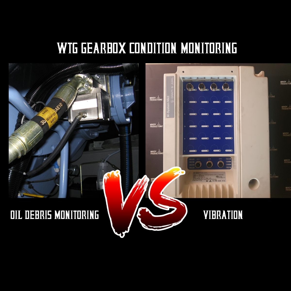
What are vibration condition monitoring systems?
Vibration CMS utilizes accelerometers strategically placed onto wind turbine drivetrains and structural elements, which measure oscillations, velocity or acceleration to identify faults such as bearing damage. Raw time-domain data or fast fourier transform (FFT) extracted from identified sensor channels are utilised to identify fault frequencies associated with the number of gear teeth, roller bearings or meshing frequencies. The rate of change in a trend or the magnitude of a spike at a certain frequency can be used to infer the amount of damage at that stage or designation within the gearbox or bearing.

KK 4 channel M-System used for monitoring direct drive turbine main bearings
What are particle counters?
Particle counters or oil debris monitors (ODM) count the particles in a stream of oil as flakes of metal are released from gears or bearings within the gearbox. The sensors are typically situated in the return line of the lubrication circuit before the filter, so that they can detect the particles being released from the gearbox before they are filtered out. They are able to detect ferrous and non-ferrous debris giving rise to cage and journal-bearing damage and they are also able to categorise particles by size and count as they are released from damage sites.
What are the main differences?

Whilst both systems are complementary there are some differences to consider when specifying a system. Cost-wise ODM is cheaper, around 35% of the cost of a CMS system. With CMS you get 8 vibration accelerometers positioned at different points on the drivetrain which allow you to determine damage at the: main bearing UW/DW, tower frequency, planetary stage, IMS, HS and generator bearing. The ODM will typically just give you overall gearbox health and cannot be used for grease lubrication applications, whereas ODM is better suited for journal-bearing and planetary stage-bearing damage detection.
How do I select which one is right for me?
Before embarking on CMS retrofit, it is useful to understand:
- What failure modes are you expecting?
- What is the cost of missing a gearbox failure?
- How quickly does the failure progress?
- What is the lubricant medium?
- Is it accessible for repair?
- What is the root cause?
- What is the implication of non-detection?
What failure modes are you expecting?
This knowledge is a luxury but if you have wind turbines that have well-established failure modes within your fleet, or if it is a known serial defect within the turbine type, then you can align your sensor deployment to the specific failure mode. For example, certain gearboxes have an issue with circlip failures on the sun pinion in the planetary stage. Spring clip failure results in a loss of retention and the sun pinion “walks” along the hollow shaft into the IMS stage. This is impossible to correct up-tower, but can be confirmed with inspection. It is located at the heart of the gearbox and therefore the transmission path to an accelerometer on the outside of the casing is both convoluted and long. This is difficult to detect with vibration but the metallic particles that are released can be detected and repair costs can be reduced. Conversely, if you are expecting a generator-bearing or main-bearing failure, which are typically grease-lubricated, then accelerometers are your best choice. You might see late-stage failures in your temperature data but this will be quite late and you can expect high repair costs and secondary damages.

Bearing roller and raceway macropitting
What is the cost of missing a gearbox failure?
This question is more complicated than it appears. It depends on numerous factors including: price of power, cost of callout labour, availability of spares and duration. Your price of power could be a combination of merchant power pricing which is dynamic, government renewables subsidy or curtailment-related. Mulitply your price of power MWh by your lost generation in MWh to get your lost revenue. Depending on your contract, you may or may not be liable for downtime and/or be entitled to liquidated damages if the responsible party is at fault. As downtime costs and repair costs can be very high, it may take just one early detection and well-planned exchange campaign to justify an entire wind farm being retrofitted with CMS.

Un-detected damage can spread throughout the gearbox causing secondary damage
Is it accessible for repair?
If you catch a gearbox failure early, then you might only have to change a few bearings, potentially up-tower without the use of a crane which could be less than 10k EUR. For some gearbox designs, certain components on the High Speed Stages (HSS) and Intermediate Stage (IMS) may be accessible for changeout with some clever use of the nacelle crane and some bearing heaters and pullers. Planetary stage failure will be most expensive as the gears and bearings are larger and you will need a jack-up vessel or crane to exchange the gearbox (between 100k to 500k). Your workshop repair costs will also be larger if secondary damage, such as walked bearings or metallic debris, have caused damage elsewhere in the gearbox. This could be between 50 and 100k EUR for workshop repairs, depending on where you are in the world.

Access to the high speed stage is good both for inspection and repair. Here engineering dye is used to check gear tooth alignment.
What is the implication of non-detection
Catastrophic failure, by which I mean a cracked gearbox housing, will entail having to clean up 300L of oil from the ladder, tower and nacelle, as well as the potential challenge of ascertaining the safety of lifting a gearbox which is in pieces. This will incur more technician and engineering time and also attractmore management attention. It is not as bad as a blade liberation or a tower collapse as you can’t immediately see it from the outside but it is still a bad few weeks in the office. Or as my old boss used to say to me, if you can’t get management attention for your problem, let it fail. Suddenly budget will become available where it wasn’t before.

Heavy macropitting isn’t as bad as gear tooth failure but has a large impact on planetary stage repair costs. This cannot be repaired up-tower.
How quickly does the failure progress?
The rate of failure progression is your action window during which you can compile information such as endoscope images, temperature data, service records and other indicators. From your first detection, you want to establish what the failure is, confirm the diagnosis and then establish the rate of failure to optimize your changeout strategy for weather, labour, crane and spare part availability. This varies from component to component and we’ve pulled out a few to highlight which CMS is most likely to detect, how long you have to act, which will give the most accurate data and where it is not suitable.

Planetary stage failure Fe count trend shows rate of progression from first warning detection to alarm limit.
Main Bearings
These are well-known failure modes that progress slowly. Failures such as main bearings are gradual and can take years before starting to show in temperature and grease samples. They are relatively easy to inspect, access and, whilst they see a lot of axial and radial loads, are slow rotating and less prone to fast failures. For oil-lubricated main bearings (e.g. Vestas V90-3, V164, V236, Enventus, or Adwen) particle counters can offer direct correlation between oil debris and damage progression whereas vibration can only infer damage from the low rotational speed.

Main bearing inner race fault identification.
For grease-lubricated main bearings, vibration is your only option and whilst it can provide a large lead time to failure (12-18 months) you need to use it in combination with inspection data or temperature to accurately track damage progression. Grease sampling and inspection at annual intervals can highlight high metallic particle counts or blackened or shiny grease to provide periodic data for benchmarking, at a frequency which should allow lead time to failure but it won’t provide you with the continuous data that vibration monitor will. There are also other secondary failure modes to consider, such as lightning damage that results in electrostatic pitting, icing buildup which can increase the loads on the rotor and shear forces from cliffs or mesas that can overload the downwind raceways. These can accelerate the wear rate of main bearings, and it is important to utilise your other sensor data such as lightning detection systems, ice detection or LIDAR to correlate your failure data.

Main bearing damages cannot be detected using particle counters as the particles do not flow freely through the grease.
High Speed Stages
High speed shafts rotate at high speed (around 1500rpm), give good clean vibration signals and can be repaired up-tower most of the time. They are also alarmed with temperature sensors so that the chance of catastrophic failure is quite low. By the time you see it in the temperature data, however, your repair costs may be higher than optimal.

High speed stage Bearing C. Roller damage indication
High speed stage failures also give good clear ODM signatures.
Journal bearings
Journal bearings are becoming more commonplace in larger wind turbine gearbox applications. Without rolling elements, using sleeves instead, they claim to offer better reliability and torque density which scales better with wind turbine size and rotor weight. Utilising a hydrodynamic oil film to carry loads whilst having a smaller space envelope, no rolling elements to break and a longer service life, the design is attractive but results in some maintenance and condition monitoring challenges. As with all things designed to be “maintenance free” there are challenges when they need maintaining.
Within wind turbine design, particularly offshore where manufacturers are moving away from direct drive technologies and back towards conventional drivetrains for better scalability, journal bearings are becoming more commonplace. This poses problems for vibration condition monitoring as there are no rolling elements that produce a pulse, and any signals are lost in the noise of the gearbox.
There are a number of failure modes associated with journal bearings such as:
- Freewheeling – wind turbine rotating idle without power to the lubrication pump
- Oil level – if the sump oil level is too low to allow the gravity feed to draw up oil
- Cold start-up with a high oil viscosity
- Misalignment wear – gearbox manufacturing design or assembly error
- Lubrication system failure – pump, metallic debris or oil quality
Typically vibration analysis cannot detect journal-bearing failure both due to location and the absence of rolling elements to produce a pulse.
Journal bearings consist of a babbit made of copper or aluminum. If the lubrication film has been compromised then this will wear against the harder steel adjacent component.
Dedicated oil debris monitors selected for non-ferrous detection of small particles (less than 100 microns) can detect when the journal bearing is about to fail but this area of condition monitoring and gearbox design is still being developed.
The research and development data seems to indicate that the speed of failure is quite high, in the order of hours and days rather than months, which will require some setup and close monitoring to ensure that it is caught. Establishing accurate alarm limits ensures that false positives are avoided and catastrophic failures are caught but, due to the relative inexperience of the wind industry in managing these failures, this data has yet to mature into a well understood practice.

Journal bearings and some parallel stage bearings cannot be inspected in some cases. Sensor data and oil analysis are sometimes the only health indicators that you have. Image: HSS Downwind ball bearing. No access due to cage width.
Gear teeth failure
Gear teeth failure due to inclusions or imperfections in manufacture also happen quite quickly. Significant portions of the gear teeth can break off because of cracks, due to material strength, overload or chemical attack, causing severe plastic deformation in helical gears. This is usually initiated at points of high stress around the gear root radius on the flank, where tensile stress and gear geometry are under the most strain. If the cracks are as a result of macropitting or indentation there may be indications in the CMS data at meshing frequencies and also as ferrous debris
Once cracks are initiated they can propagate under tension or shear loading and cause plastic deformation or fatigue failure. Once a crack extends across a gear, geometry fracture is achieved and parts of the gear separate from the main body. This liberation or gear fracture can fall into the mesh and result in catastrophic damage (case failure) which could see the release of gearbox oil down the wind turbine ladder. If the gear liberation does not fall into the mesh, the resulting ferrous debris or vibration signals will show in the CMS. Just don’t expect any praise, as you can hear it from some distance from the wind turbine. I’ve seen gearboxes run with 2 missing IMS teeth in Texas, and it sounded like someone with one shoe running on a walkway. It did run, however, so technically missing teeth does not always mean failure.
Planetary Failure
The planetary stage is inherently noisy. Three or four planet gears rotate around a sun gear bound by a ring gear. Vibration sensors are usually positioned near the ring gear at radial positions. Due to slow rotation and pulses being dampened by multiple components, detectability of failure modes vibration CMS can be limited for detecting classic planetary stage-bearing damage such as spalling. In this instance, particle counters may provide the first or only detection for your planetary-bearing failures. This is also the most expensive part of the gearbox to refurbish. Damages can be identified between 8 weeks and 4 months prior to failure through an increase in daily particle counts and rate of generation. Whilst up-tower repair is limited for planetary stages, early detection can reduce the number of gears and bearings that require replacement, as well as reducing any secondary failures in neighbouring stages such as pitting and indentations. Some gearboxes prone to planetary stage failure are fitted with a swarf alarm, which is a crude monitoring alarm tripped by a metal particle completing a circuit. Whilst better than temperature in this instance, this sensor is prone to late detection and false positives which can lead to unnecessary downtime. In consequence, some operators have lost confidence in the swarf sensors and choose to decommission them.

Planet bearing spalling
Other Factors to consider
In addition to detectability, there are other factors which may influence your selection. Vibration condition monitoring is a highly skilled discipline which requires specialist resource or training to interpret. Advanced data analysis and processing techniques and software are required to understand spectra, and trends, and to interpret data. This set of skills is typically discrete from the type of mechanical engineers who are covered in oil and stick their arms in gearboxes. Specialist providers offer monitoring services in support of the hardware deployment but this is around 700 EUR/WTG/year. Particle count data however is simpler as the basic trends of particle count are easier to interpret. For more advances analysis you can filter by bin size and ferrous vs non-ferrous data. ODM is a direct measurement of damage both in severity (total counts) and progression (count rate) providing some advantages in remaining useful life estimation.

Vibration analysis often requires specialist software and training in order to interpret the sensor data.

Circlip failure.
The wider maintenance strategy of your fleet is also worth considering. An in-house engineering team may be feasible if you are operating 1000 WTGs but not cost effective if you are only operating a small number. Similarly, if you are only maintaining the wind farm for a shorter period of time, either due to duration of contract or remaining useful life of the wind farm, you may not have the time to recover your investment.
CAPEX may be more suitable from an accounting perspective but it may not suit your operating model so it may be worth considering hardware as a service (HaaS) if you are looking at short term operation or budgetary constraints.
Who wears the risk? If a gearbox fails, who pays for it? A lot of independent service providers have now inherited full scope service (FSA) contracts from OEMS which means they are inheriting the major component risk. In the absence of any historical data it may be difficult to predict the amount of failures during a contract and therefore how much to cost into the bid. CMS can support with creating this data.
Conclusion
There are many factors to consider before embarking on CMS retrofit in specification in a turbine supply agreement. The case for gearbox CMS is well established as the cost of downtime is high and the implications of non-detection are catastrophic. For more information on what WTG gearbox failures you can expect and how CMS can support your O&M strategy, get in touch.


Leave a comment